GMC Clubmobile
During World War II the American Red Cross worked with the Army to modify about a 100 GMC CCKW trucks into the “Clubmobile”. These trucks were mobile units operated by the ARC, staffed with 3 volunteer women, and were designed to bring comfort, entertainment, and morale-boosting services to American troops stationed overseas. The program began in 1942 and became a hallmark of Red Cross efforts during the war. The Clubmobile Girls were recruited for their ability to connect with and uplift the spirits of soldiers.
The Clubmobile program remains an iconic example of wartime volunteerism, highlighting how small gestures—like a hot cup of coffee and a doughnut—could have a profound impact on the morale and well-being of soldiers during World War II. I’ve always been fascinated by the sociology of war. Away from the battlefield, away from the stories of heroic taking of a hill or saving of a foxhole buddy, there are so many things that go into maintaining an effective fighting force. And the Clubmobiles were an example of that.
I’ve been reading “Goodnight, Irene” as I’ve been working on this project and it’s interesting to see the impact on these volunteer women…and the impact of their work on the troops they encountered.
Want to make your own Clubmobile donuts? Here’s the recipe!
And if you want to get super nerdy about the Clubmobile design, equipment, staffing, and story, check out this blog post where I’m trying to share all that I’ve learned as I research.
CAD Design
For this project, I’m designing the entire Clubmobile “box” (as I’m calling it) from scratch with Fusion 360. This has required a great deal of research since this vehicle isn’t documented very well. There are a decent (although surprisingly small) amount of exterior photos, but the interior photos are nearly non-existent. I’ve reached out to museums, restoration/reenactor folks, and searched for hours online to find good photos. I’ve found a few which has allowed me to move forward with some data and some assumptions.
Starting the CAD work: Exterior body design
Before we start talking about the CAD work, let me first share that this project has been on my project wishlist for years. A number of years back I picked up a CMK Clubmobile conversion set with the intention of building it straight from that conversion. In the years since then, my desire for Reasonable Accuracy has grown significantly and of course, I’ve learned CAD. I knew I had the CMK conversion set in my stash, but I also knew that however good it was, I’d want to spice it up.
When I finally got excited to get this project started a few months back, I popped open the CMK set… and discovered that the resin parts were warped as hell. My now-marginally-competent CAD brain said “Don’t worry about fixing this stuff, you can design your own!” So that’s what I did. I first started with the overall body shape.
I used the CMK kit as a basic set of dimensions and design ideas. This was a very helpful measurement fast foward, even if I ended up tweaking a bunch of dimensions to get things more accurate. In a little over a week of working a few hours a night, I had the basic body shape laid out.
As a side note: I used my Bambu P1S filament 3D printer to spit out a quick test model, just to be able to try it out on my GMC Conversion Mule (the old beat up 1/35 Tamiya CCKW model that I use to test my various GMC CCKW conversions). In about an hour, I had a tangible test model in hand to help me dial in the overall dimensions. Without any surface detail added yet, it was surprisingly pretty. And STRONG. I could have stood on this thing and probably not broken it.
Now was the time for the details. This is when the reference photos came in super handy. Given that there were ~100 of these made, I assumed they’d all be factory line consistent in how they were constructed. Mostly true, but some vehicles had some details, others didn’t. So I had to make some decisions. I also oversized the rivets a bit to give them some more obvious pop once painted. The restoration vehicles have much smaller ones than the ones in the historical photos. I think. It’s honestly hard to tell, so I am doing what feels right.
In a few more days, I had the various external details mostly done.
Then I went back to the Bambu to print a test model, mainly to see how good the tiny detail would turn out. Short answer: Not great. As amazed as I was by the smooth printing, I was really disappointed by the detailed test print version. I even swapped my .4mm nozzle for the .2mm nozzle and waited 22 hours for that version to print. It was better but nowhere near the quality of a resin print. So… resin for sure.
I ran another test print, this time in resin, to see if a box shape like this would actually print worth a damn. SUCCESS! It printed surprisingly well. Even if it just BARELY fit in my printer. This “barely fits the printer” has become a theme, so I was driven to order a large build plate printer. Hey, you do what you need to, right??
Time to switch to the design of the interior
With a solid amount of the external work done and the basic shape of The Box dialed in, I needed to switch to the interior. I needed to get a sense of where everything was and make sure it would fit… and that I didn’t need to make adjustments. For example, my roof detail work is way off so I need to fix it. But I can’t do that until I have the interior further along.
The interior reference material is TOUGH to find. I probably found less than a dozen helpful images of how the GMC Clubmobile (vs. the initial London Bus version) was laid out inside, or what each of the interior equipment/cabinetry elements actually looked like. I spent hours googling and generally figured out the elements of the interior. At least close enough. (I’m sure I’m going to stumble across a cache of great images as soon as I’m done with this project…)
Here’s an example of the London Bus layout

Once I had a sense of what I needed to create, I started laying out the various equipment/cabinets with post-it notes cut to “size” and used those to refine and layout all the things that sat on the floor. I created them each as dull boxes on the interior just to get the sizing and placement right. Once I had that dialed in, I started creating external files for each piece of equipment (like the donut fryer machine) and the cabinets. This will allow me to work on each one of those individually and just import into the main CAD file. I want to add a lot of detail to each element, so being able to work on them individually is much easier.
Here’s a video rotation of the current status:
The work continues
It’s crazy how much detail is getting baked into this project. You can see now (with Barbie Dream Clubmobile colors) how the interior is shaping up.
I’ve been running a number of test prints along the way to get the dimensions dialed in. I’ve been trying to build to exact real life dimensions, where I can find them, but sometimes you have to tweak a wall thickness to be able to be printed or increase the size of a component to make it “feel real” vs. the accurate dimensions. So this test printing process has been handy.
The donut fryer
Since the Clubmobile is effectively based around the donut making process, I really wanted to do the donut fryer right. After much research and even more googling, I found out that the machines were lent to the US Army by Doughnut Corporation of America. Their Lincoln Model D was the one in question. I search google for a long time trying to find pics/specs and came up empty. One night I tried again with the same search terms. BAM! The Internet Archive had a sales brochure from 1949 that is basically the same machine. It even had some very basic dimensions to help me get started and to see how it was constructed!
Here’s the first test print of the machine… about 75% complete.
It’s a weird time in the project where I feel sooooo close to being done, but then realize I am going to spend an entire weekend researching and then designing a 1940s donut fryer!
But here’s the thing… as I keep saying… the more I look at the reference photos, the more I notice about thing I skipped, missed, and/or ignored. Plus, it’s so damn hard to get my brain initially wrapped around a part sometimes that I will hyperfocus on getting the core shape done. My brain sorta tunes out the bits and bobs, and then later I see them and come back to it to get it as accurate as humanly possible.
Here’s the final version of the donut maker!
The Design Process
Huge thanks to Dave and Mike for having me back on the Plastic Model Mojo podcast recently. We talked a lot about my WWII Clubmobile project and the process of figuring out how to “read” historical photos and translate them into CAD then print them to use on a model. Thought I’d share this example of process, shared through the photos above.
First photo: One of the few historical photos I could find for creating the rear folding stairs.
Second photo: My sketch trying to mentally process what I was seeing
Third photo: The final CAD model I designed to get basically close enough.
Fourth photo: The final printed part
Now imagine doing this for every part of the build! Haha. And the crazy part is that the more I look at the photos, the more things I notice that I’d missed originally… or understand better what I’m looking at after some time working with the modeling.
Prints, prints, and more prints
It’s one thing to design a great model in Fusion, it’s quite another to get the damn thing to print. After printing several test models, I had to then print a number of copies to get things juuuuust right. Some print setting were tweaked, some printing supports were tweaked, and then some lessons were learned about how to get the printed supports off without causing damage.
Final shell print
Finally! I got a full body print! After I’d spent about an hour cleaning it up, I realized… the loudspeaker doors were printed on instead of left off. Damn it! Another print.
Although, I say “final”, but I realized later that I really should have some of the interior framing showing, so I decided to cut that out of sheet styrene with the Cricut cutter and glue it in, rather than reprinting yet another shell.
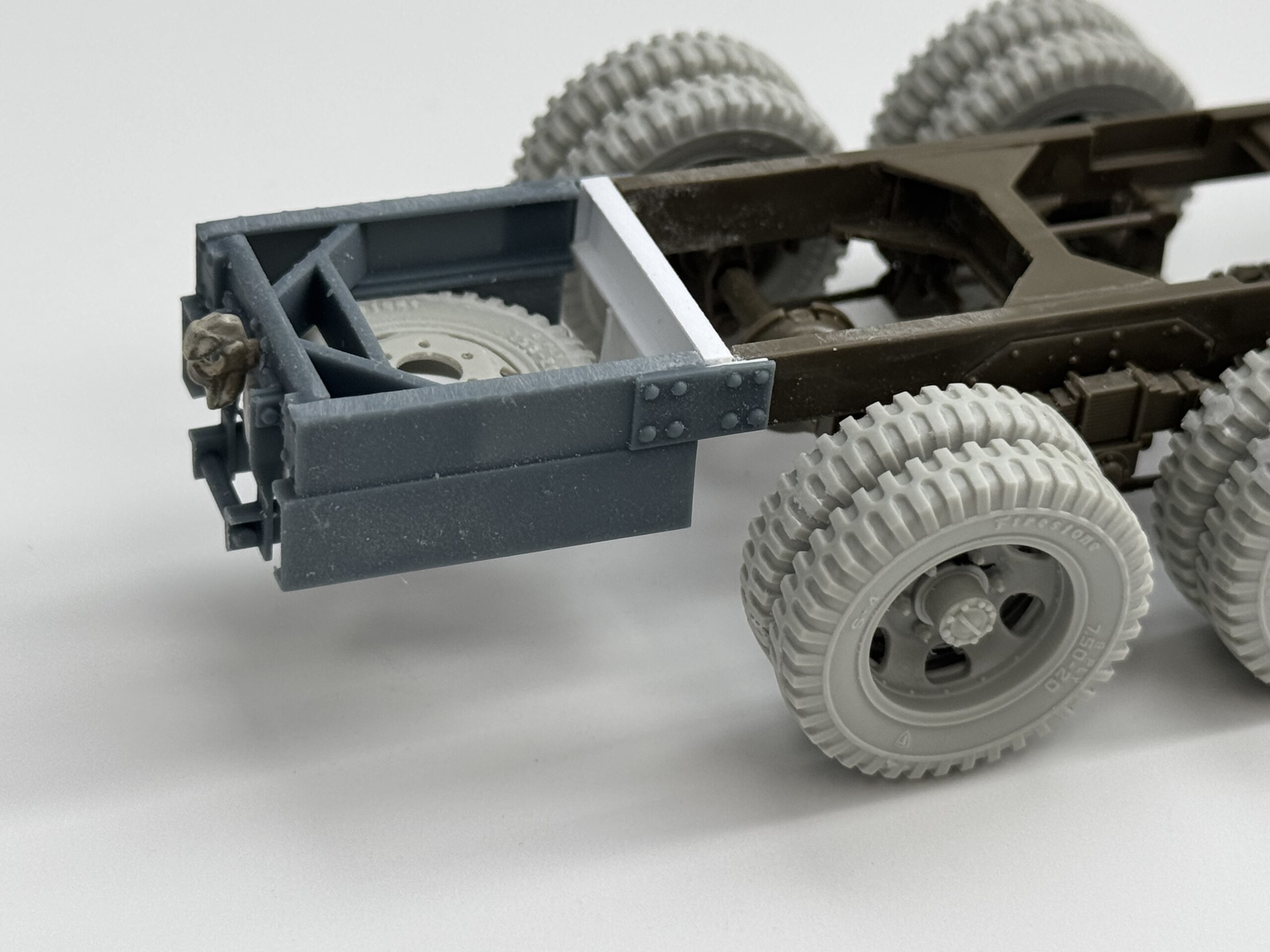
Spare tire holder/Chassis extension
There were a few things that I kept putting off until the end of the design process… the spare tire holder for one.
The Clubmobile chassis needed an extension to fit the Clubmobile body. And the spare tire was relocated from the side of the truck to the rear.
I had originally envisioned the spare tire holder part and the chassis extension part as two separate parts. But after printing the extension and installing it, I realized that because of the nature of the design of the spare tire holder, it would be too fragile to print on its own. So I designed a new extension+holder part. This was actually the second step… after trying to make a decent version with Evergreen styrene strips, I gave up and opened Fusion.
Grinding…
Here’s where the real work began: it was time to start printing interior parts and dialing them in for fit, apparence, sizing, etc. I did a lot of these test prints, first to make sure the part was what I needed it to be and that everything fit together. Then it was about making sure all the details on each part were solid. Then it was about making sure I get the damn things off the supports without breaking tiny details. Easier said than done.
I started painting the wood grained parts and then realized several things needed tweaking… including how I was painting the faux wood. As I mentioned above, the more I placed parts and reviewed the historical photos, the more I found myself realizing I’d missed, skipped, or flat out ignored crucial details. As I shared on the Plastic Model Mojo podcast, I really have a deep desire to create this project in the most hyper-accurate way possible. There’s something about the Clubmobile women’s story that makes me want to get this very very correct. They deserve it.
I also realized after I’d painted and glued down the wood flooring (laser cut basswood sheet) that the Clubmobiles actually used linoleum. So out it came. Here’s a couple pics of my first attempt at 1940s style linoleum. Needless to say, I’ll be going back to the start on this particular paint job!
Phonograph
Onto the CAD work for the phonograph. Or more specifically, the Army Model D-200 Acoustical Phonograph Player by L.M. Sandwick. This one was relatively simple (save the clusterfuckery required to make the needle arm) and had plenty of great pics online!
More info and pics:
Final printing bits
I had pushed off develop CAD models of a few things just because I was eager to move to painting. But after i printed out all the parts (see below), I realized that it would be generally better for me to hurry up and finish these final parts. There’s a number of them.
And by the way, there’s a full graveyard of test prints that didn’t make the cut. This is just a small sampling.
First up to model was the folding step-up ladder. I only had a couple good research photos, so I had to sketch out what I thought I was seeing before doing any CAD work.
I’m done CAD drawing! Maybe…?
I think I’m done with everything from CAD, minus any last minute tweaks I need to do once I start building. Here’s the final model!
Nope. More CAD work to do.
This project is the single project I’ll be bringing to Scale Model Challenge (SMC), my first time to visit this world class show. As I was winding down the CAD/printing work for the “box”, I started looking more at the cab itself. I’d jumped ahead, despite other desires, to building the cab and chassis because I needed them fully built out to measure against for the box CAD work.
But apparently with my mind in other places, I’d just kinda slapped together the cab. And I just wasn’t impressed. It wasn’t SMC-worthy. So in a fit of low grade frustration, I pulled the cab off, opened a new Tamiya kit and started to build a replacement cab. But this time, I was really considering all the PE and improvements that would be needed.
After a joking comment from a buddy (“you should just create a new cab in CAD!”) I realized that it would be faster to d exactly that than trying to fix and improve the kit parts. So off I went.
The goal isn’t to replace the entire cab, at least not yet. I just wanted to replace the cab floor where 80% of the fixes and details were going. I also wanted to create some better parts for the rear wall of the cab and how the bar that holds up the canvas is mounted. After a few hours, I had a pretty good start. (Kit part vs. CAD part below)
NOTE: More info on this as the CAD work continues
Stencils
During this project, and thanks to a smokin’ hot Facebook Marketplace deal, I picked up a Glowforge Aura laser cutter. This entry level 5w laser has been wonderful for a range of things. But not so much for the stencil cutting. Short version: because the underpowered laser, I had to make multiple passes to cut the stencil material (Tamiya/Mig sheet tape) and in doing so the adhesive heated up and became gummy. This meant that the stencils wouldn’t stick and didn’t create sharp, tape-only edges. The gummy glue created “edges”.
After multiple efforts (and I’ll post separately about this in another post), I signed up for the local Makerspace so I could get access to a 100w laser. Yeah, slightly more powerful. And after a minor amount of dialing in the settings, I have stencils! Now I have to design the actual real artwork.
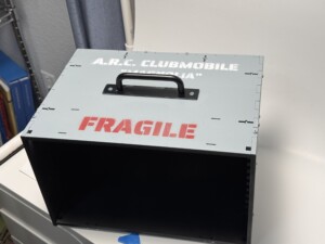
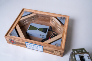
Travel box
I ordered a travel box and of course, needed to paint it to match the project.
You may notice I used “Magnolia” on the stenciling because that’s what one of the Clubmobiles was named. (The each had their own specific name) But… Magnolia was a hard top GMC cab. I was building the soft top. D’oh!
Diorama Concepting
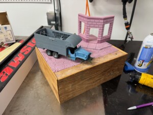
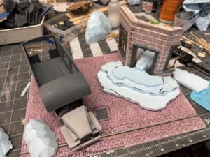
This project was bound for Scale Model Challenge (SMC) in Europe. Which meant I had to design it for carry on travel and carry on travel box sizing. This was going to be a tough test of my concepting skills. The Clubmobile was a decent size vehicle and I wanted to have a bunch of figures that showed the chaos of the scene around a Clubmobile when they rolled up.
I found a great set of figures on Etsy for a Clubmobile scene, generally speaking. A group of soldiers and a crew of three Clubmobile women. It took some time trying to figure out the “story” of this diorama. I had been reading a number of accounts about the Clubmobile history and the stories the women had. Or better yet, the stories about sexual harrassment, returning home to families who said things like “you were only serving donuts, why are you saying you had a hard time”, and so much more. One of the figures from the set was a woman leaning over the counter and pointing. I had a flash of inspiration.
I wanted to show a scene where there was blatant but completely ignored harrassment. So I wanted to create a scene where one of the women was being harassed with only passing awareness of that action.
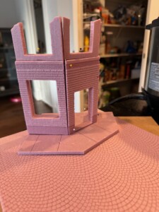
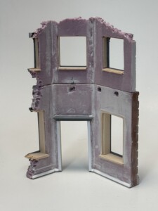
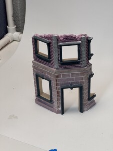
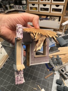
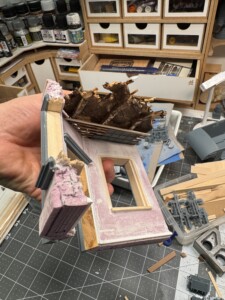
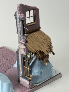
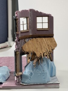
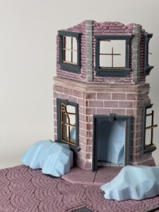
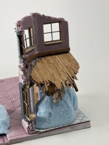
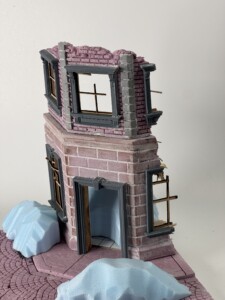
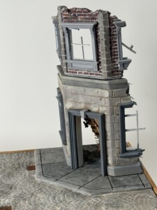
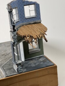
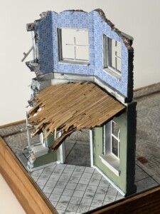
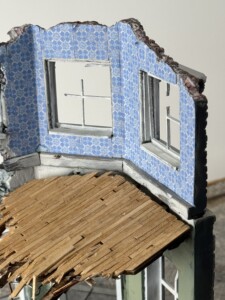
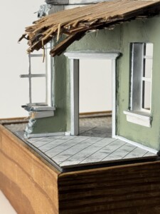
I needed something to show clear harassment and ill-intent from one of the soldiers. So I figured a bed would be a great option for making that clear. But where would a bed show up in a war zone? Ahhhhhh… a bombed out hotel!
Diorama creation
I was working from a very specific height/width/depth specification but I knew I wanted three things to be true in this diorama:
- Height – I wanted the building to feel imposing and not tiny in comparison to the truck.
- Base – I wanted some bulk and some cool design for the base. This is something I’ve been thinking more about unique base design lately. I didn’t want to waste travel space on a thick base, but I also didn’t want a 10 mm thick base either.
- Lighting – I wanted to create lighting in the truck and that meant some base thickness to run the battery.
Pretty quickly, I realized I needed to create a base that was separate from the diorama build itself. That way I could stick the base in my travel backpack and then carry the diorama in the travel box.
The diorama base
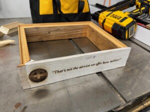
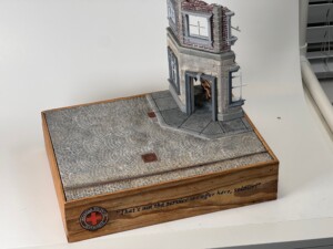
I built a robust wooden base with the battery mounted inside it. The wood I used was reclaimed wood from a local 1950s lumber yard that was going out of business. It was literally pulled off the walls of the storage area and I’ve been saving it for years.
Once I’d cut it into pieces to glue up, I laser etched an ARC Clubmobile logo. It turned out great.
I also laser etched the title but that turned out terrible. The text wasn’t big enough to be readable at a decent distance and I tried adding paint inside the etching to make it pop. It didn’t work. Like at all. In fact, after a couple coats, the wood started to disintegrate.
The solution was to paint over the etching with a matching color and then I decided to go in a different direction all together and laser cut a title plate. This design was based on the hand created signs that the Army put up as they moved through Europe to warn of various dangers. This also pushed me to shorten the overall title… less words are better than more. I love how it turned out!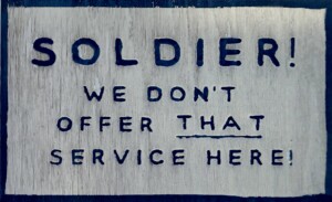
I also used my AK paint markers to “touch paint” the ARC logo. If you look closely, you’ll also see a QR code I laser engraved on a piece of wood that led to this blog.
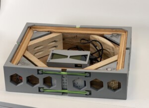
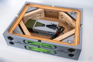
I also wanted to ensure that my base was protected while in my backpack. I designed some quickie FDM printed protectors. I used rubber bands to keep them held together. The v1 rubber band attachment points weren’t the best engineering, so I made a v2.
v1
v2
I’ll talk more about the battery more when I talk about getting the lighting wired up, but one thing to note is that I had installed a round battery holder only to discover that the round battery had an auto-off feature if it wasn’t feeding enough power to plugged in device. This is nice for a cell phone but non-functional for these tiny draw LED lights. So I went back to my favorite Skullcandy battery I used on the Cylon Raider dio. And I swiped the Cylon dio battery holder too and hot glued it to the base.
The Diorama
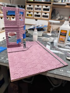
To make the actual diorama as thin as possible, I used a piece of MDF cut to the right size. This was a terrible choice in retrospect. More about that shortly.
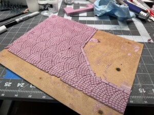
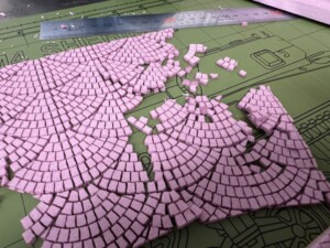
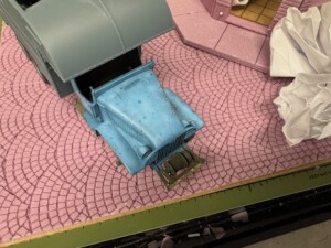
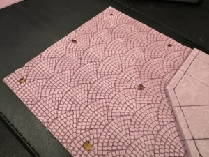
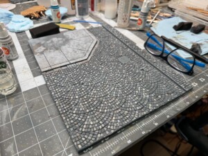
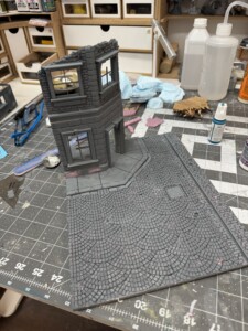
On top of the MDF I glued down two pieces of insulation foam, one cut to size for the sidewalk and building foundation, and one for the cobblestones. The cobblestone pattern was laser engraved (not cut all the way through, just cut about halfway down the piece of foam). This looked great on both counts and allowed me to weather, damage, and generally beat it up to look pretty realistic. You can see the first pass at the pieces of foam here:
I also started testing the base + foam. It looked pretty good. But I realized pretty quickly that I wanted to have a single railroad rail coming through the diorama to add some fun to the city street “texture”. But when I put it straight in the cobblestone fans, it didn’t look right. Some quick research made me realize that inside the two rails, the stones are more often than not laid straight not fanned. So I cut out and replaced that area with a new laser cut piece of foam.
In a boneheaded move, I realized that I didn’t have magnet holes carved into the MDF before I glued down the foam. I should have just started over (MDF and foam are cheap and after getting the laser cutter settings dialed in it would have been pretty fast). But instead I flipped the MDF+cobblestones over and laser engraved the MDF. And melted some of the cobbles. No worries though, it was easy to glue in replacements.
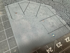
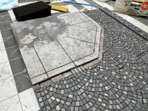
I painted the concrete base coat with grey acrylic paints, stippled on various shades of grays and lighter blacks to give it some wear look. And of course before I did this, I beat up the edges and added some texture on top by plucking with tweezers and rolling with a ball of aluminum foil.
Then it was time to paint the cobbles. I used several shades of greys, tans, and whites. Turned out pretty good for a base!
To weather it, I started washing it with various dust tones. It turned out great.
Better choices next time…
As I put down that many various shades of acrylics (i.e. thinned with water), I didn’t think about the fact that these water based materials would be leaking through the foam and hitting the MDF. The same MDF that doesn’t like water. As anyone would have expected, that much water and thinned white glue being applied to the MDF started to warp the hell out of the MDF. I tried to fix this by glueing a sheet of thin steel to the bottom with the goal of being able to a) stop further warping and b) hopefully bending the MDF back to sorta flat.
It worked but only a little. Next time, no MDF. Or a different usage of the foam and MDF so water and glue aren’t getting applied directly to the foam before being glued into place on the MDF.
Working on the building
Build Book
Settings:
-
Engrave
-
75% speed
-
100% power
-
-
Cut
-
10% speed
- 100% power
-
MORE TO COME! This page will be updated as progress continues!
References
To keep this page as short as possible (I know, you’re laughing given the length), I’ve put all my references material in this blog post. Check it out!Clubmobile v1 v337
