Thanks to a wonderfully helpful call with Barry Biediger recently, I now understand some of the fundamental basics of LED lighting. It’s funny how the LED tech has made it so damn easy to wire up basic lighting that works well and lasts a long time.
Because Barry is awesome, he followed up our call with some details that he was cool with me sharing with y’all. I’m also adding a few tidbits I’ve learned from Barry and others along the way that may help you.
Wiring tips and tricks
My current supplier of choice for LED lights and related accessories has been Evan Designs. They provide reasonably priced, high quality products, are quick to respond to questions, and ship fast.
Recently, I picked up several different types of LEDs: Pico, Nano, Chip. I asked them how much different the amount of light each one kicks off vs. the other. They told me that amount of light is basically the same, it’s just the spread of that light. Smaller the physical LED, the less the light spreads out.
I also learned that colored LEDs require different amounts of power. Red LEDs take more power to run than warm white LEDs. This may or may not matter to how you wire things, but it could play into your planning.
All of the lights I bought run at 3v. That means they can be powered by a coin battery, a dual AAA battery box, or a dual AA battery box. Evan Designs sells all of these.
When and how to use a resistor
Anything more (like a 9v square battery) is likely to just overpower the LED and blow it out. (Barry said he’s had this happen with shrapnel going all over) This is where resistors come into play. Effectively, they’re “reducers” that take bigger power source on one side of the resister (a 9v battery, for example) and constrict the amount of electricity flowing to the light on the other side of the resistor (a 3V LED, for example) so that the LED isn’t overpowered.
You can figure out what kind of resistor you need with one of the online resistor calculator. Here’s what Barry says about how to select a resistor:
Many LEDs have data sheets that show what their forward voltage is. I always use 3.3v if it’s not known. The data sheets also list the forward current, but it’s almost always 20 mA. I shoot for somewhere between 18 & 20 mA. That being the case, as that calculator shows, the resistor needed for each LED with a 5v power supply would be either 91 ohm or 82 ohm. Make sure you get these in ohms instead of K ohms. 91K ohms would be 91,000 ohms, so your LED wouldn’t even light up. Standard resistors are 1⁄4 watt.
Wiring basics
There are two types of wiring approaches:
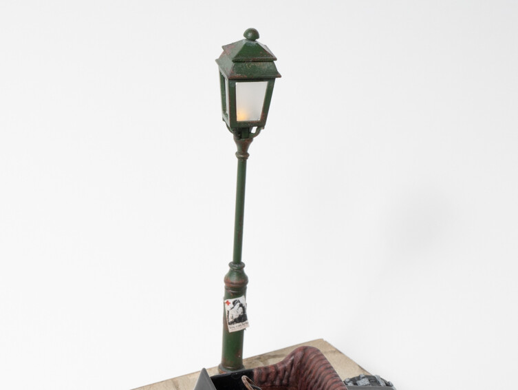
Parallel: Think about parallel like a bouquet of flowers in a vase. Imagine 10 LEDs all bundled together and attached to a single power source. Like Clark Griswold plugging everything he has into one outlet. This is often a pretty simple and effective solution for what us modelers do. On my recent Ford vignette, I had one LED in a street lamp connected directly to the coin battery.
Series: Think about series like Christmas tree lights where the end of one light plugs into the next into the next and then finally into the power source. Barry mentioned for my current minor needs, I’m unlikely to need this, so I’ll come back to this later.
For what I’ve been wiring up, here’s my process:
- Twist the two wire ends together, fold them over and twist again
- Solder this bundle of twisted wire together
- Cover the solder joint with heat shrink
This is a pretty robust connection and shouldn’t come loose months or years from now. The heat shrink only needs to be slightly longer than it takes to cover the soldered joint and the exposed wire. (This also helps ensure the exposed wire doesn’t touch other things that might cause a short. To heat the heat shrink, I’ve been using my new heat gun that Matt McDougall turned me onto. It does a good job of heating the heat shrink without melting the solder joint.
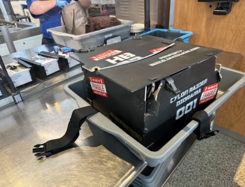
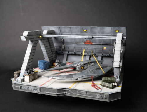
When I’ve been running long stretches of wire from LED to power source on the Cylon Raider diorama, I’ve used 28 gauge wire from Evan Designs to cover the distance. Barry mentioned that as long as you’re in the basic size ballpark of this kind of wire, the size doesn’t matter much.
Once my wiring is in place, I use low temp (!!) hot glue to attach it to grooves or holes I cut in my foam diorama bases. The hot temp glue will melt the hell out of insulation foam, but the low temp is fine.
Connector strip
Barry turned me onto connector strips that allow you to skip the soldering and heat shrinking and instead use a dedicated “board” for your connections. The cool thing about this option is that you can replace/troubleshoot lighting issues one light at a time if you need to. He works on box dioramas that can have a lot of lights and complex layouts and may run for many more hours overall than a traditional diorama. This is a good option for those instances. I picked up a strip and may end up using it on the Cylon Raider dio, but I’d also be perfectly find just bundling all the LED leads and attaching a power source.
Here’s the connector strip Barry recommended and I picked up. Looks solid. And here’s his awesome sketch of how this series wiring would work:
Dimming LEDs, paint, and potentiometers
Evan Designs has mentioned that the best (only?) way to dim their LEDs is to apply some enamel or acrylic paint to the LED itself. But they also sell a dimmer accessory. More info on painting the LEDs in their resources.
Barry recommended potentiometers. He says
I use 10K pots as dimmers when I just want the ability to cut some of the brightness. I wire them directly inline before each LED: You can also find pots with an off position when they’re turned down all the way. Using a regular pot will just dim it down until it’s very dim. Here’s the ones I recommend,
Wall and USB power sources
The coolest idea that Barry shared was using a power cord port instead of a battery. You can use a power brick to plug into the wall or you can use a USB phone battery to power the diorama. (Barry said use the cheapest UBS batteries you can find at the gas station counters as those don’t include the auto-shutoff functions that more expensive models have.
Instead of wiring your lights to a battery, you’ll wire them to one of these “barrel jack” connectors
You might not need to go this far, but could be helpful to have a big rechargeable battery running your lighting all day at that next contest. Into that barrel jack connector, you’ll plug one of these USB cables into it. It’s a normal USB port on one side and the barrel jack connection on the other. Very smart!
One last thing… Multimeter
If you want to use an multimeter to check your mA, I’d recommend one with an auto-ranging function. It makes things a bit easier. Here’s an example of one. A multimeter is also handy for checking resistor values (instead of reading the color bands) as well as for checking continutity.


Thanks for the understandable translation! Hats off to you an Barry!
On dimming LEDs: while variable resistors/pots can be used in a pinch for some control of LED brightness, they are not ideal … one will find a very small and sensitive region between “off” and “on”; getting the desired brightness can be frustrating.
The basic problem is that LEDs are constant-voltage, variable-current devices, but a variable resistor primarily changes the voltage.
The off the shelf “dimmer” devices are usually PWM-based i.e. they pulse the LED on and off, fast enough to trick the eye (but sometimes not the camera). One can quite easily build a PWM circuit with a good old 555 timer chip. Here’s an example: https://leap.tardate.com/electronics101/led/dimmer/555pwm/
One can get fancy with Arduino-controlled PWM, with flame and flicker effects e.g. https://leap.tardate.com/electronics101/led/flickerkit/
The “best” LED brightness control is using a current control. This gives very smooth control over the full range, with no flickering that may cause problems with photography/videography. And it can be relatively simply, for example, using a simple current-mirror circuit (so voltage controls current): https://leap.tardate.com/electronics101/led/dimmer/vco/
I’ve found the 10K pots, work fairly smoothly on a single LED to go from 100% brightness to say 10%. They give me enough control in many of my box dioramas to adjust for different room lighting conditions. I’ve always thought that a current control circuit would be best, but I’ve never seen one until now. I’ll definitely try it!